
#Drag airplane skin#
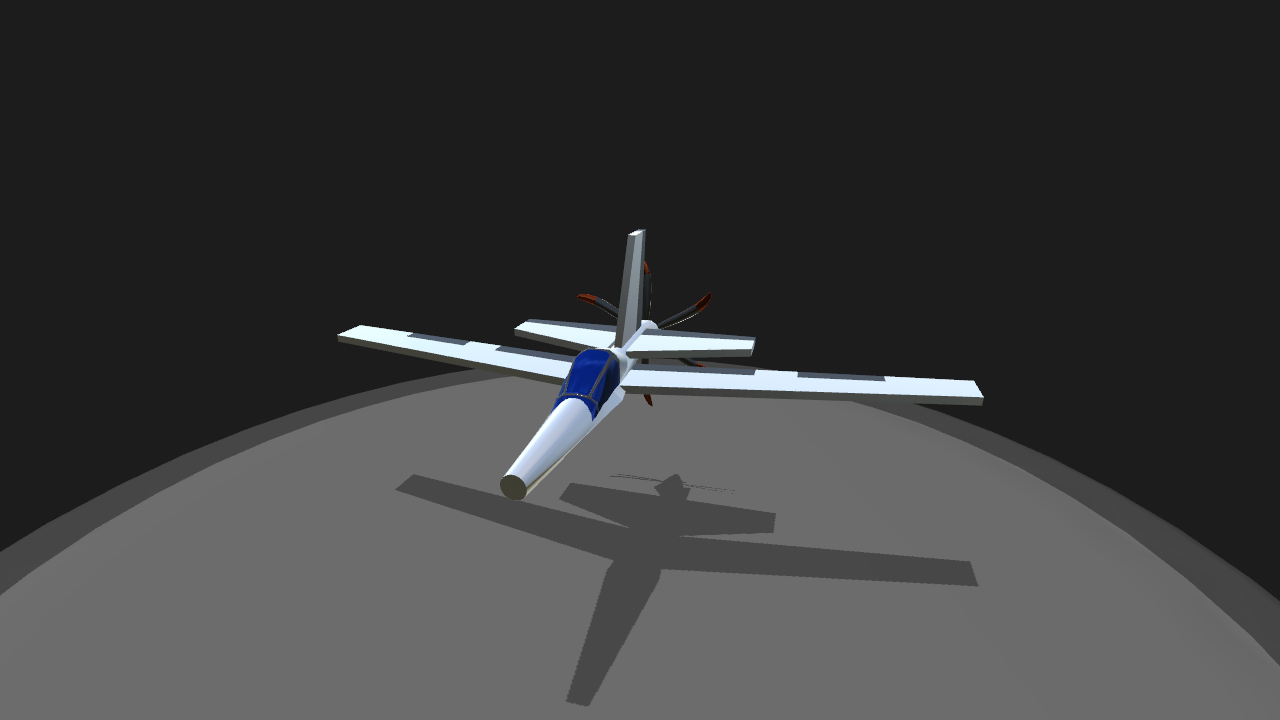
The variation arises from the fact that the skin friction coefficient and the fuselage interference factor are both a function of the Reynolds number, which is in turn a function of the aircraft velocity and atmospheric conditions (density and temperature). $$ C_ \) value is not constant across all speeds and altitudes. The total aircraft drag is therefore the sum of the zero-lift drag (parasitic) and the lift-induced drag. Lift Induced drag: Drag produced as a consequence of the lift force generated by the body. Parasitic drag: Drag produced as a consequence of the shape and form of the body interacting with the medium through which it passes (here air). Graphic showing a typical subsonic drag calculation breakdown It’s important to note here that our concept aircraft operates far away from the transonic or sonic flight regime and so drag due to the compressibility of the air (wave drag) is not a factor in this analysis. Larger aircraft could also have engine nacelles, external stores, fairings or antennae that should also be included in the drag calculation.īroadly we split the drag contribution of each component into two distinct categories: Parasitic (zero-lift) drag and Lift Induced drag. Our aircraft consists of a number of major components which each contribute to the total drag produced: wing, fuselage, empennage (horizontal and vertical tail) and canopy. We will work in SI (metric) units when performing our preliminary drag estimation. A concept sketch of a fictitious 2-seat Light Sport AircraftĪll the required geometry with which to perform the drag estimation is shown in the table below. Below is a sketch of a conceptual two-seat light sport aircraft (LSA) designed to cruise between 80 and 100 kts. Preliminary Design Geometryįor the purposes of this tutorial we will follow a worked example approach. This will assist us in selecting a power unit (engine and propeller - see Part 10 in this series) and ultimately calculating the maximum theoretical speed of our design. In this tutorial we will define the preliminary geometry of a two-seat light aircraft, go through the initial drag estimation exercise, and create a number of plots that describe how the aircraft drag varies with velocity and the amount of lift produced. With this conceptual layout and mass estimation completed you can move onto the initial performance estimation - the drag calculation. Your conceptual representation should include such variables as maximum take-off weight, cruise speed, and a sketch of the conceptual aircraft layout. With this information clearly defined you can start to generate a conceptual representation of the aircraft by following the steps outlined in the previous posts. What is the approximate mass of the aircraft (EW, MTOW, payload).Is take-off performance or cruise speed of greater importance to fulfill the mission requirement?.Does the aircraft require cabin pressurization?.Define the typical airports/landing strips from which the aircraft will operate.At what altitude will the aircraft predominantly operate?.What is the size and mass of the intended payload (passengers, cargo, weapons)?.

#Drag airplane series#
Up to this point in the series we have used many “rules-of-thumb” or studied existing aircraft when generating a concept aircraft. Now we put it all together and run through a preliminary drag estimation of a new aircraft design. In the previous posts we have covered the fundamentals of flight, studied the wing, fuselage and empennage, and have been introduced to aerodynamic lift, drag and moment coefficients. Welcome to Part 9 in the Fundamentals of Aircraft Design series.


 0 kommentar(er)
